It is important to note that electron-pair geometry around a central atom is not the same thing as its molecular structure/shape. The electron-pair geometries shown in the previous page describe all regions where electrons are located, bonds as well as lone pairs. Molecular structure/shape describes the location of the atoms, not the electrons. It shows the overall shape that the bonds make within a structure that still abides by a set electron-pair geometry defined above. So all central atoms have one of the defined geometries above (linear, → octahedral). If a central atom has more than zero lone pairs, it adopts a different molecular structure/shape.
We differentiate between these two situations by naming the geometry that includes all electron pairs the electron-pair geometry. The molecular structure shows only the placement of the atoms in the molecule. When there are no lone electron pairs around the central atom, the electron-pair geometries will match their molecular structures. However, when lone pairs are present on the central atom, the electron-pair geometries and the molecular structures will differ. Thus, the presence of lone pairs affects the overall shape.
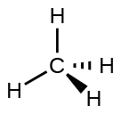
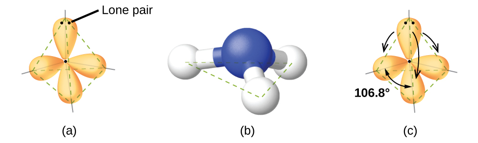
For example, the methane molecule, CH4, which is the major component of natural gas. It has four bonding pairs/domains of electrons around the central carbon atom. Both the electron-pair geometry is tetrahedral, as is the molecular structure (Figure 1). On the other hand, the ammonia molecule, NH3, has four electron pairs associated with the nitrogen atom. Consequently, it has a tetrahedral electron-pair geometry. A lone pair, not included in the molecular structure but influences the molecule’s shape (Figure 2), occupies one of these regions.
Influence of Electron-Pair Repulsions on Molecular Geometry
As seen in Figure 2, small distortions from the ideal angles can occur in a given electron-pair geometry. These distortions result from differences in repulsion between various regions of electron density. VSEPR theory predicts these distortions by establishing an order of repulsions among different electron pairs. It also determines the amount of space occupied by different kinds of electron pairs. The order of electron-pair repulsions from greatest to least repulsion is:
lone pair-lone pair > lone pair-bonding pair > bonding pair-bonding pair
This order of repulsions determines the amount of space occupied by different regions of electrons. A lone pair of electrons occupies a larger region of space than the electrons in a triple bond. In turn, electrons in a triple bond occupy more space than those in a double bond. This pattern continues with different types of electron pairs.
The order of sizes from largest to smallest is:
lone pair > triple bond > double bond > single bond
In the ammonia molecule, the three hydrogen atoms bond to the central nitrogen in a three-dimensional trigonal pyramid. The nitrogen atom at the apex of this pyramid, while the hydrogen atoms forming the base. This arrangement is different from a flat, trigonal planar structure. The ideal bond angles in a trigonal pyramid are based on the tetrahedral electron pair geometry. Again, there are slight deviations from the ideal because lone pairs occupy larger regions of space than do bonding electrons. The H–N–H bond angles in NH3 are slightly smaller than the 109.5° angle in a regular tetrahedron. This reduction occurs because the repulsion between the lone pair and the bonding pairs is greater than the repulsion between the bonding pairs themselves. Consequently, the bond angles are slightly compressed.
Bond Angle Variations
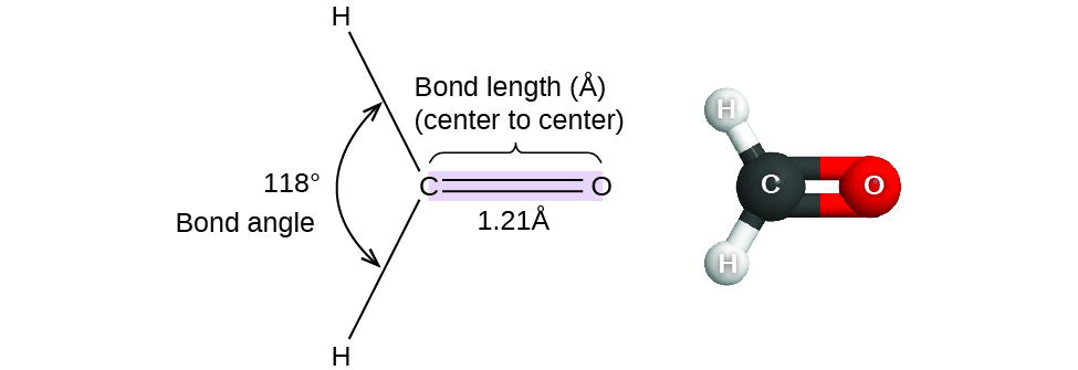
Consider formaldehyde (H2CO), which serves as a preservative for biological and anatomical specimens. This molecule has regions of high electron density that consist of two single bonds and one double bond. The basic geometry is trigonal planar with 120° bond angles. However, the presence of a double bond causes the angles to be slightly larger reaching 121°. In contrast, the angle between the single bonds is slightly smaller, measuring 118°.
Although formaldehyde (H2CO) and ammonia (NH3) have specific bond angles. However, memorizing the bond angles for EVERY molecule is not expected. Instead, you should know the bond angles for the basic geometries. Understand how the presence of a lone pair or multiple bond around a central atom affects bond angles. This will help you determine whether a bond angle will be smaller or greater than expected.
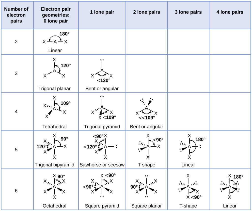
Figure 4 shows the ideal molecular structures predicted from the electron-pair geometries for combinations of lone pairs and bonding pairs. Notice instead of saying exactly how much a bond angle decreases due to the presence of a lone pair we are just saying “<” the specific angle. It is great to know that the angle in NH3 is 106.8° but as soon as a H is replaced with a different atom this could slightly affect the bond angle, so it is better just to state where angles will be non-ideal with “<” or “>”.
In water (H2O), we saw that we have two lone pairs present. Instead of specifying that the bond angle is exactly 104.5°, we would say that the angle is <<109.5°. This is because the two lone pairs that both require more space, causing the bond angles to be reduced.
Distinct Positions and Geometries in Electron-Pair Models
According to VSEPR theory, the terminal atom locations ($X$s in Figure 4) are equivalent within the linear, trigonal planar, and tetrahedral electron-pair geometries. This equivalence applies to the first three rows of the table. Replacing any X with a lone pair does not matter because rotation of the molecules can convert the positions.
For trigonal bipyramidal electron-pair geometries, however, there are two distinct X positions, as shown in Figure 4. One type is an axial position, which is along the axis of the trigonal pyramid. If we hold a model of a trigonal bipyramid by the two axial positions, we create an axis around which we can rotate the model. The other type is an equatorial position, where three positions form an equator around the middle of the molecule. Figure 4 shows that bonds surround the axial position at 90°. In contrast, the equatorial position has more space available because some of the angles are 120°. In a trigonal bipyramidal electron-pair geometry, lone pairs always occupy equatorial positions. These positions are more spacious and can more easily accommodate the larger lone pairs.
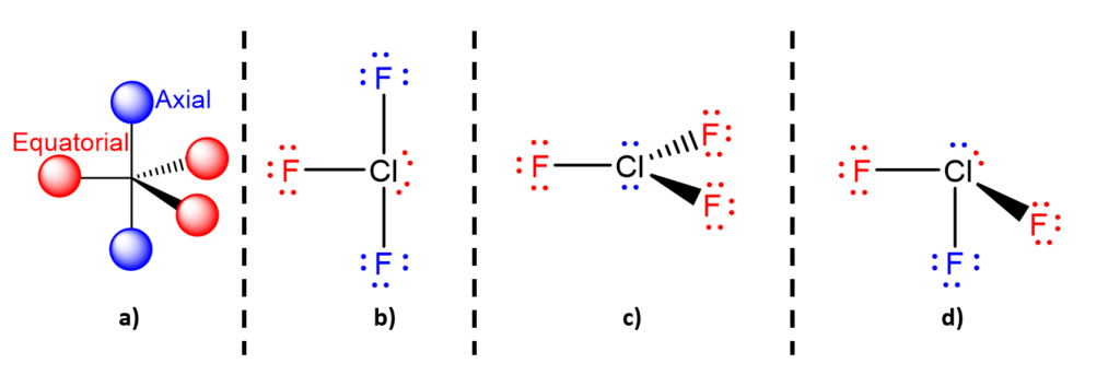
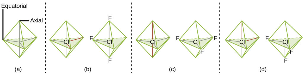
Theoretically, we can come up with three possible arrangements for the three bonds and two lone pairs for the ClF3 molecule (below). The stable structure is the one that puts the lone pairs in equatorial locations, giving a T-shaped molecular structure b).
When a central atom has two lone electron pairs and four bonding regions, we have an octahedral electron-pair geometry. The two lone pairs are on opposite sides of the octahedron, 180° apart. This arrangement results in a square planar molecular structure that minimizes lone pair-lone pair repulsions.